|
 
Stage I
In this first stage of the project it has been developed the scanning strategies for the three classes of objects of interest: molds, small artifacts and small scale resproduction.
It became obvious the necesity of a simulator that can validate the proposed scanning strategies.
Using a simulation environment for designing the scanning algorithms has several advantages:
• The possibility of collisions between the robotic arm, laser probe and workpiece is eliminated. As
the laser probe is an expensive device, collision avoidance is a very important point to consider;
• The system can be analyzed in ideal conditions, with no surface reflections, external light sources
or perturbations in the measurements;
• The parameters of the scanning system components, like camera location, focal length, optical
sensor resolution, laser beam width, rotary table size and location, can be freely changed, and the
influence of these changes can be analyzed thoroughly;
• Scanning of objects with complex shapes and different surface properties, that may not be physically
available, is possible.
There are also a number of disadvantages, the biggest one being the computational power involved for
accurate simulations in real-time, and the second one being the difficulty for simulating the less-than-ideal conditions of the real system.
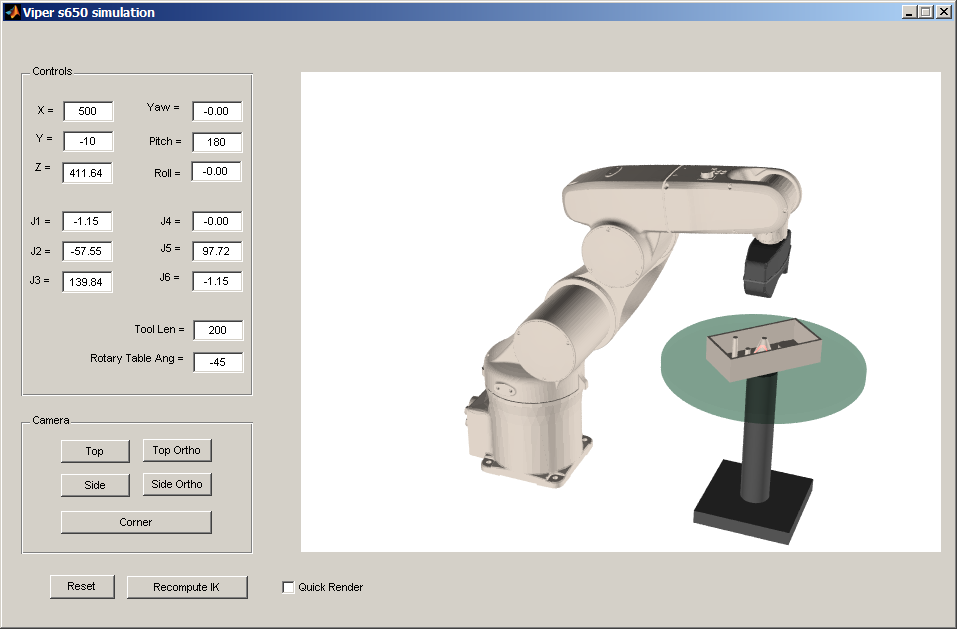
For the robotic arm, the simulator allows displaying the robot in any user-defined position. The user is able to control either the joint angles for each articulation, or the Cartesian position together
with the orientation given by ZYZ0 Euler angles. The user is able to specify the tool
transformation.
For the laser probe, the software simulates the interaction of the laser beam with any user-
defined workpiece, having various surface properties. The two cameras which are integrated into the laser
probe can also be simulated, and the image which would be captured by them is displayed to
the user. Furthermore, the laser beam can be detected in the images from the two cameras, and the
triangulation equations can be applied to them in order to compute a point cloud. The point clouds
obtained from simulating the scanning process from different viewing angles can be transformed into
a fixed coordinate system, that will be attached to the workpiece being scanned.
As for the rotary table, its rotation have to be simulated, and the workpiece that sits on the table
should rotate synchronously with the table. Behaviors such as inertial movement due to fast table
movements do not have to be simulated; the workpiece should be considered attached to the table.
 Technical documentation for stage I Technical documentation for stage I
|